The Project: A Wireless Charging Coil Alignment System
This was a quarter-long collaboration with the The Volkswagen Electronics Research Laboratory. It was part of the course ME 218D: Smart Product Design: Projects taught by Professor Ed Carryer at Stanford University.
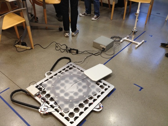
The goal of the project was to design and build a device which will help to align wireless charging coils for electric vehicles. Misalignment, either translational in the horizontal plane or rotational around the vertical axis, significantly and adversely affects wireless charging efficiency. Minimizing misalignment and maximizing efficiency were of top priority.
The charging system consists of two coils. The primary charge coil is located in a parking spot and is connected to charging infrastructure. The secondary coil is located on the underside of the vehicle and it is connected to the vehicle's battery through power management circuitry. Once a car is parked above the primary charging coil misalignment between the two coils must be measured and corrected for by the system (by translating or rotating the primary coil).
System Requirements
Below are the requirements given to us at the beginning of the project.
- Mechanical Specifications
- The primary coil housing is 50 cm x 50 cm x 4.8 cm and the coil weighs approximately 30 pounds.
- The system shall be able to translate the coil housing +/-20 cm on the ground plane with a resolution of 1/2 cm.
- The system shall be able to rotate the coil housing +/-15 degrees (about the vehicle z-axis) with a resolution of 1 degree.
- The mechanics of the system should be hidden or covered such that pinch points and moving parts are minimized. This should also protect the system from foreign objects.
- The system must include a housing which is placed on a parking spot. Provisions should be made such that the enclosure conforms to IP54 standards or higher.
- The system shall respond to and reply to commands via a standard communication protocol (CAN preferred).
- The specifics of message and signal formats are up to the students, however, an adjustable system is desirable (variable ID's, message rates, etc.).
- The system should accept two modes of movement: automatic and manual. Automatic mode relies on internal sensors to align the coils and manual mode will accept movement commands from a supervisory controller.
- The system should report its status and position continuously while active.
- The system should operate on readily available US power (120 V single phase 60 Hz).
- The system will operate in a region of high electromagnetic activity. Precautions should be taken to ensure proper operation of electronics and actuators.
