The Platform
Our platform had to move ± 20 cm in the X-Y axes as well as rotate ±15 degrees. In addition to this, it had to be slim enough to fit underneath a car. In order to maintain the necessary rigidity to support the 30 pound charging coil, we chose to construct the X and Y stages out of 6061 aluminum. We designed a stage with provisions for motor mounting and perforated it with hexagonal cutouts to reduce weight.
The Platform Stages
The platform is constructed of three rectangular plates separated by two sets of steel bottom-mount drawer slides. The drawer slides between the bottom plate and middle plate allow for translational movement in the x axis, while the slides between the middle and top plate allow for translational movement in the y axis.
Each set of drawer slides is comprised of four slides arranged in an alternating pattern such that when two of the slides are fully extended, the other two slides are contracted, directly supporting the load. The four slides are evenly spaced to support the entire plate above it. This arrangement allows for minimum deflection of the plates while still allowing for an extremely low profile. The slides are attached to the plates with blind rivets.
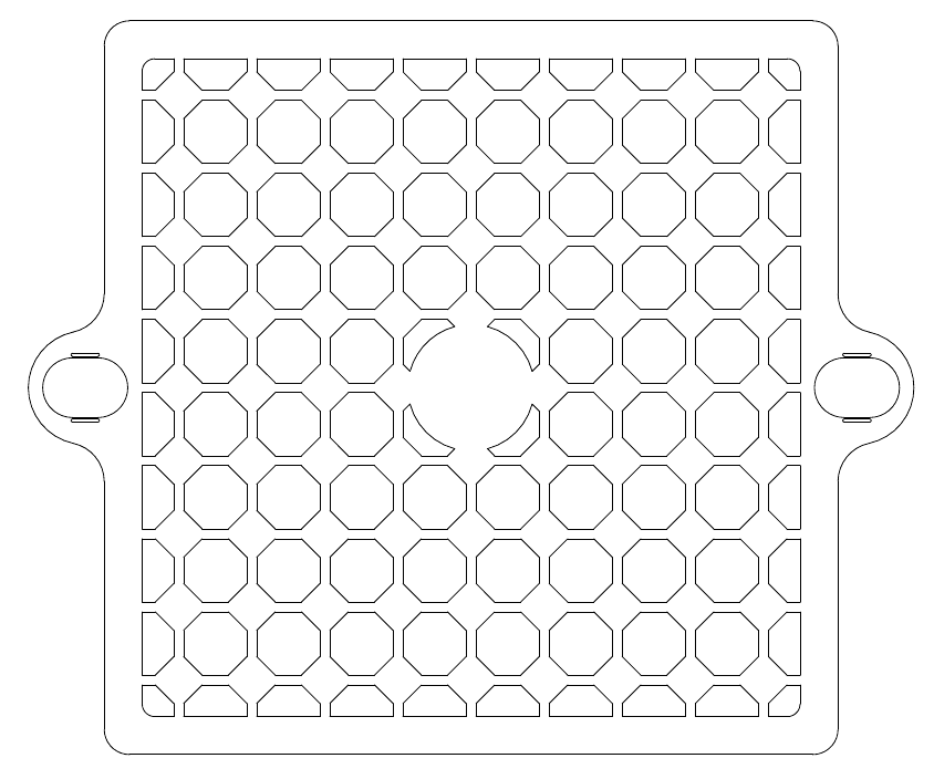
The top two plates, which travel in the x and y directions, are made of 1/8" 6061, perforated with hexagons to save weight and allow for access to the stages below. Tabs on the side of the plates provide mounting for the disk stepper motors used to drive the stages. The bottom plate is made of a solid square piece of 3/8" polycarbonate. The geometry of the x and y platforms are shown below.
Each set of drawer slides is comprised of four slides arranged in an alternating pattern such that when two of the slides are fully extended, the other two slides are contracted, directly supporting the load. The four slides are evenly spaced to support the entire plate above it. This arrangement allows for minimum deflection of the plates while still allowing for an extremely low profile. The slides are attached to the plates with blind rivets.
The top two plates, which travel in the x and y directions, are made of 1/8" 6061, perforated with hexagons to save weight and allow for access to the stages below. Tabs on the side of the plates provide mounting for the disk stepper motors used to drive the stages. The bottom plate is made of a solid square piece of 3/8" polycarbonate. The geometry of the x and y platforms are shown below.
Additionally, a rotational stage is placed on top of the x and y stages, supported by a 17" diameter turntable. A belt is fixed to the outside of the turntable and driven by a third disk motor fixed to the tab on the top translational stage. The rotational stage is made of 3/8" acrylic, and provides a place for the charge coil to be mounted directly over the center of the turntable. The rotational stage also provides a cantilevered mount for the RFID antenna used to locate the tags on the bottom of the car.
The Motors
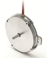
In order to get accurate positioning in a very low-clearance application, we sourced pancake steppers from Nanotec. We utilized the ST6318, which offered a step angle of 1.8º in a ~3/8" thick package.
The Power Transmission
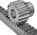
To translate the rotational steps from our motors into usable X-Y lateral movement, we used steel racks and pinions from McMaster-Carr. Since we used very small racks to fit our clearance restrictions, there was no real provision to use threaded fasteners to attach the racks to our stages. We tack welded small steel tabs to the racks which we in turn riveted to the aluminum platform stages.
Cable Management
When designing the mechanical aspects of the platform, we rapidly realized that cable management was a significant issue. Given the number of motors and sensors on the platform, we had to take care of a large number of cables. Adding X-Y translation and rotation into the equation resulted in many opportunities for the cables to get caught.
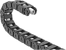
We utilized snap-together cable carriers from McMaster (part number 55835K33), rotated on their sides to fit within our height constraints. These carriers allowed us to include enough slack in the cables to reach the full extent of the platform's travel.
We utilized snap-together cable carriers from McMaster (part number 55835K33), rotated on their sides to fit within our height constraints. These carriers allowed us to include enough slack in the cables to reach the full extent of the platform's travel.
